Digital Logic Worksheet 5
Work Sheet Report OutlineIntroduction
Part 1
Part 2
Introduction
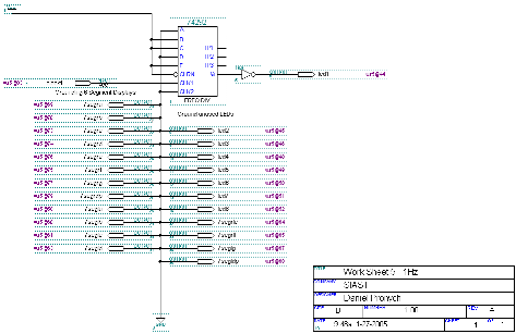
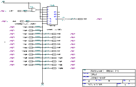
In this worksheet I created a frequency clock. Part 1 is very close to providing a 1 Hz. Part 2 is a dual clock frequency at 4 Hz or 1 Hz, depending on if the switch is engaged (1 Hz signal if the button is not held down). Click on the graphic on this page to view a larger version. You may also download the files I used to make the schematic at the end of each part.
Top of PagePart 1
The following is the circuit I used to obtain a 1 Hz clock signal. All unused LEDs and 7 segment displays are grounded.

Figure WS 5.1: 1 Hz Clock Circuit
Graphic File: .gdf (Compressed in .zip format)
Top of Page
Part 2
The following is the circuit I used to obtain a dual 1 Hz and 4 Hz clock signal. All unused LEDs and 7 segment displays are grounded.

Figure WS5.1: 1 Hz and 4 Hz Clock Circuit
Graphic File: .gdf (Compressed in .zip format)
Top of Page
Website content © 1999-2025 by Daniel Pronych.
Valid XHTML 1.0!