Lab 3 - JK Flip Flop Counter Lab
Lab Report OutlineIntroduction
Part A
Part B
Introduction
In this lab using the PLDT-2 Board I designed two counting circuits. Part A was a 16 counter circuit and Part B was a 11 counter circuit. Click on the schematic to see the full picture in size B. You may also download the files I used to make the schematic at the end of each part.
Top of PagePart A ( 16 Counter )
Figure 3.1.1 is the picture of my digital schematic for my 16 counter.
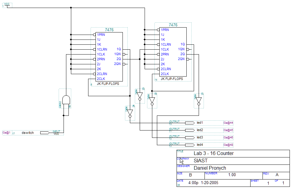
Figure 3.1.1: 16 Counter Circuit
Graphic File: .gdf (Compressed in .zip format)
Top of Page
Part B ( 11 Counter with Reset Switch )
Figure 3.1.2 is the picture of the my digital schematic for my 11 counter with a reset switch that allows the circuit to be reset at any point in the count.
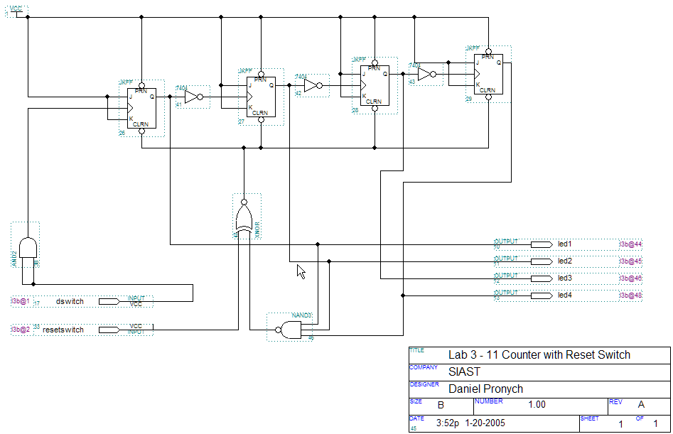
Figure 3.1.2: 11 Counter Circuit with Reset Switch
Graphic File: .gdf (Compressed in .zip format)
Top of Page
Website content © 1999-2026 by Daniel Pronych.
![]()
Valid XHTML 1.0!
![]()